MechanicalDesignProcess <<
Previous Next >> 第三章
第二章
Our designs will all start with just an idea for a product. Those ideas will need to be proven, so, we’ll move on building prototypes, and if those prototypes seem to work via testing to some written specification, we’ll document our designs via drawings.我
們的設計都將僅從產品構思開始。這些想法需要經過驗證,因此,我們將繼續構建原型,如果這些原型似乎可行通過對某些書面規格的測試,我們將通過圖紙記錄設計。
We’ll need this documentation to be able to build more products in a repeatable manner
我們需要此文檔,以便能夠以可重複的方式構建更多產品方式
This chapter will take us from the point of just having an idea for a product, all the way to optimally placing all of the individual objects that will make up the final working design.
本章將帶我們從僅對產品有想法的角度出發,優化放置所有組成最終對象的對象的方法工作設計。
We start out our design with a “blank paper,” and that paper will get filled with physical objects. First item of concern will be to determine if the paper is indeed “blank” or are there some beginning constraints. Next item of concern will be to determine exactly what physical objects are to be included. We should then assume that there is an optimal placement of those objects based on the objectives of the overall design, so we’ll conclude with some words on the choices we have on that object placement.
我們從“空白紙”開始設計,然後將紙填充 物理對象。首先要關注的是確定紙張是否確實 “空白”還是有一些開始的限制。下一個值得關注的項目是確定要包括哪些物理對象。然後我們應該假設根據對象的目標對這些對象進行最佳放置總體設計,所以我們在此總結一下我們的選擇對象放置。
2.1 Beginning Point
2.1起點
Designers are tasked with either continuing work on existing designs or starting a brand new design. Let’s spend a little time seeing what the differences are with those starting points.
設計師的任務是繼續進行現有設計或開始設計。全新的設計。讓我們花一點時間看看有什麼區別這些起點。
• Brand new design: This is a “clean sheet” start for the designer; they would basically have no constraints, other than complying with the specification. We’ll have an entire section on what exactly a specification is and its various components.
•全新的設計:這是設計師的“整潔”開始;除了遵守規範外,它們基本上沒有任何限制。我們會有有關規範的確切含義及其各個組成部分的整個章節。
• Continuation (or adding to) an existing design: This is a variation on the brand new design, but only a small part of an existing design is to be modified. The designer here has many of the same challenges of the brand new design, but the additional work must utilize the existing design. We will have a separate section on defining what exactly the “system” is in this context.
•延續(或增加)現有設計:這是品牌的變體新設計,但僅對現有設計的一小部分進行修改。的這裡的設計師面臨著與全新設計相同的許多挑戰,但是其他工作必須利用現有設計。我們將有一個單獨的部分在此背景下定義“系統”的確切含義。
• Major modification of an existing design: Again, this is a variation on the brand new design, but in this case a large part of the original design is to be modified. The designer here is tasked with changing a part of the overall design, so there will be more constraints than a brand new design.
•現有設計的重大修改:同樣,這是品牌的一種變體新設計,但在這種情況下,原始設計的很大一部分將被修改。這裡的設計師的任務是更改整體設計的一部分,因此將會比全新設計更具約束力。
So, it’s important to know where the present design effort will fit into what has been previously done. Our “basic layout” can proceed either with or without the constraints of previous work.
因此,重要的是要知道當前的設計工作將在哪裡適應以前已經完成。我們的“基本佈局”可以進行或不進行先前工作的限制。
2.2 Defining the Design Boundary: System Description
2.2定義設計邊界:系統說明
A few words on defining the “system” being designed: Designs can be extremely complex and large (think space shuttle or large passenger jet), smaller systems (think automobiles), or yet smaller systems such as a personal computer, coffee maker, or cell phone. The scope, cost, time, number of resources committed, and interfaces to other equipment vary with all of these design projects. It is imperative that the designer keep in mind the system being designed. This is important for a variety of reasons, a few of which are:
定義正在設計的“系統”的幾句話:設計可能非常極端複雜而大型(想像航天飛機或大型客機),較小的系統(例如汽車)或較小的系統,例如個人計算機,咖啡製造商或手機。範圍,成本,時間,承諾的資源數量以及與所有其他設計項目的接口都與其他設備不同。勢在必行設計人員要牢記正在設計的系統。這對於原因多種多樣,其中包括:
• Focus on the personal responsibility (scope of work)
•關注個人責任(工作範圍)
• Awareness of other equipment that must interface to this design
•了解必須與該設計交互的其他設備
• Overall “system” functionality (not just the function of the subsystem)
•整體的“系統”功能(不僅僅是子系統的功能)
Even something as “small” as a cell phone functions as part of a larger system. That is, the box that the consumer purchases can contain:
甚至像手機這樣“小”的東西也可以作為大系統的一部分。即,消費者購買的盒子可以包含:
• Cell phone
• 手機
• Battery charger
• 充電器
• Cables
•電纜
• Sim card
•SIM卡
• Instruction manual
•使用說明書
• Other shipping materials (labels, bags, bubble wrap)
•其他運輸材料(標籤,袋子,氣泡包裝)
(We’ll limit the discussion of the “system” here, as one can even think of a larger system that would include the cell phone towers and satellite systems.)
(我們將在這裡限制對“系統”的討論,因為人們甚至可以想到更大的範圍。系統,其中包括手機信號塔和衛星系統。)
We start here at system description because most electronic enclosures surround and support a product. Sometimes, one product can be thought of as part of a larger product. For example, a network adapter card (a product itself) can be placed into a microcomputer (a second product) and form an entirely new product, in this example, a networkable microcomputer. Things get even more complicated as the networkable microcomputer itself forms a part of the network which may be an even larger product.
我們從系統描述開始,因為大多數電子機箱都圍繞著支持產品。有時,可以將一種產品視為較大產品的一部分。例如,可以將網絡適配器卡(產品本身)放入微型計算機(第二產品)中,並形成一個全新的產品,在此示例中為可聯網的微型計算機。隨著網絡的發展,事情變得更加複雜微型計算機本身構成了網絡的一部分,它可能是更大的產品。
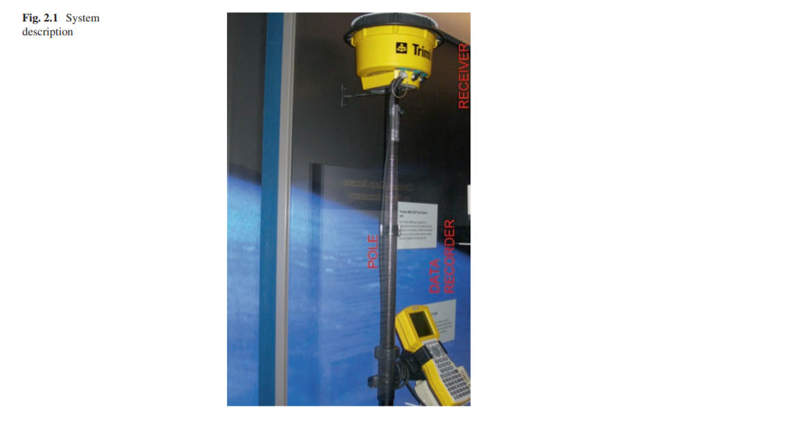
Looking at things in another way, we may be tasked to design just a subsystem of a much larger system. Thus, our “system” may be not even a product but just part of a larger “system” that has been broken down into (time) manageable pieces. For example, we could be tasked to design a data recorder as part of a (larger) surveying system. This system is shown in Fig. 2.1. This system consists of (at least) three major subsystems:
用另一種方式看待事物,我們可能只被設計為更大系統的子系統。因此,我們的“系統”甚至可能不是產品,而只是更大的“系統”的一部分,該系統已被分解為(時間)可管理的部分。例如,我們的任務是設計一個數據記錄器,作為(更大)測量系統的一部分。該系統如圖2.1所示。該系統至少包括三個主要子系統:
description
描述
• Data recorder
•數據記錄儀
• Data recorder mounting bracket
•數據記錄儀安裝支架
• Survey pole (labeled “pole”), which includes another subsystem, the data recorder bracket
•調查極(標記為“極”),其中包括另一個子系統,數據錄音機支架
There would actually be even more individual portions of this “system” including cables, shipping container (box), and instruction manual (but let’s neglect these for this example). As a side note, the system shown in Fig. 2.1 is a photograph of a Trimble Survey system appearing in the Smithsonian Museum in Washington, D.C.
實際上,該“系統”中甚至會有更多的獨立部分,包括電纜,運輸容器(盒子)和說明手冊(但在此示例中,我們將其忽略)。作為附帶說明,圖2.1中所示的系統是
Trimble Survey系統的照片,該系統出現在華盛頓特區的史密森尼博物館中。
We have become a team member of the “surveyor system design group” and will be designing a portion of overall design (the data recorder portion).
我們已成為“測量員系統設計小組”的團隊成員,並將設計總體設計的一部分(數據記錄器部分)。
Therefore, the first task for us is to determine (specify) what exactly we are to design (sort of like “building a fence” around the project that we will be responsible for in a given amount of time). To accomplish this task, we will need a specification.
因此,我們的首要任務是確定(指定)我們到底要設計什麼(在給定的時間內圍繞我們負責的項目“建立圍欄”之類)。要完成此任務,我們將需要一個規範。
(Refer back to Chap. 1 discussion on specifications.)
(請參考第1章有關規範的討論。)
2.3 The Design Process
2.3設計過程
2.3.1 Overall Project Start to Project Finish
2.3.1總體項目開始到項目完成
Designs can proceed in any number of ways. All companies vary in how they execute the entire product design process, but they do have some common characteristics. No particular way is absolutely correct; it is the end result (specification conformance) that is a measure of success. A design usually proceeds as:
設計可以以多種方式進行。所有公司在執行整個產品設計過程的方式上都有差異,但是它們確實具有一些共同的特徵。沒有什麼特別的方法是絕對正確的。最終結果(符合規範)是衡量成功的標準。設計通常按以下步驟進行:
The EPE Designer will have a “lion’s share” of the responsibility of the following tasks. They will be both a “doer” and an “enabler” of much of what is done. If they don’t do the work themselves, they certainly are responsible for the work.
EPE設計人員將承擔以下任務的“絕大部分”。他們將是許多工作的“執行者”和“推動者”。如果他們自己不做這項工作,那麼他們肯定會對這項工作負責。
1.Sketch of idea – this is the “ideation” stage of the project. Words must be turned into a picture representation of those words. Once the idea takes some form, it can easily be reviewed and revised. Some of the people in the review group need a “picture” of the idea to really see what is being proposed.
1.構思草圖–這是項目的“理想”階段。話必須轉變成這些單詞的圖片表示。想法採用某種形式後,可以輕鬆地進行審查和修訂。評論小組中的一些人需要一個想法的“圖片”才能真正看到正在提議的內容。
2. Review of idea and authorization to proceed to prototype – this action takes the “picture of the idea” and turns it into something the team can actually touch. What seemed fine in sketch form can now be picked up, held, and used in a way a customer will use the product; the prototype is a full-scale, three-dimensional picture. The “authorization to proceed” is important in that projects that are usually limited in time and money, so these expenditures must be agreed to by the team. Steps 3 and 4 (below) actually create the prototype.
2.審查構思和授權以進行原型製作-此操作將“想法的圖片”,並將其轉變為團隊可以實際觸及的東西。現在可以以某種方式拿起,握住和使用草圖形式中看起來不錯的東西客戶將使用該產品;原型是全尺寸的三維圖片。 “授權進行”在以下項目中很重要通常時間和金錢有限,因此這些支出必須由以下各方同意團隊。步驟3和4(如下)實際上創建了原型。
3. Drawing (file creation) of idea for prototype fabrication – usually, a sketch is turned into a digitized drawing file that allows the design to be fabricated. (Design will now be at Revision 1.) Italics are included to show “revision level” of the formal documentation, which is further expanded on in Chap.12.
3.繪製(文件創建)原型製造的想法–通常,草圖是轉換成數字化的圖形文件,從而可以製作設計。(現在將在修訂版1上進行設計。)包含斜體字以顯示“修訂版”。級別”),將在第12章中進一步擴展。
4. Prototype fabrication (physical parts) – the project team will determine the cost and time constraints of producing the prototype. Sometimes, just a “quick-anddirty” prototype is needed to make good progress; sometimes a prototype constructed to exacting specifications is needed. The EPE Designer should have very good perspective on what is needed for this stage of development.
4.原型製造(物理零件)–項目團隊將確定成本和生產原型的時間限制。有時,僅需一個“快速且骯髒的”原型即可取得良好的進展。有時需要按照嚴格的規格構造的原型。 EPE設計人員應具備對這個開發階段需要什麼有很好的看法。
5. Prototype analysis and testing – once the prototype is received by the team, it is tested to see how the prototype conforms to the specification. The project team determines just exactly what testing needs to be done to make the decision on how to proceed after that testing.
5.原型分析和測試–一旦團隊收到原型,就可以測試以查看原型如何符合規範。項目團隊確定恰好需要進行哪些測試才能做出決定測試後如何進行。
6. Review of prototype and test result – test results are reviewed by the team, and revisions are proposed. (Assuming Revision 1 needs improvement, we’ll revise design to Revision 2.)
6.審查原型和測試結果–測試結果由團隊審查,並且提出了修訂。(假設修訂1需要改進,我們將設計修訂為修訂2。)
7. Change to improve prototype (drawing and prototype) – this is the start of an iterative process which will finally result in the design conforming to the product specification.
7.進行更改以改善原型(圖紙和原型)–這是迭代過程,最終將使設計符合產品規格。
8. Further analysis and testing of Revision 2(Assuming Revision 2 conforms to product specification.)
8.修訂2的進一步分析和測試(假設修訂版2符合產品規格。)
9. Final documentation produced/final testing/final review
9.最終文件製作/最終測試/最終審查
10. Formal approval of design for Production Release
10.正式批准生產發布的設計
Note that “Production Release” in the above process allows the production of “some number” of units to be produced for sale to a customer or to serve as a larger number of units for a more expansive test program. Corporations can differ in a number of ways on their procedure for releasing and testing their products for their customers. Also note that most projects would have many more revisions than the two revisions shown, but the project generally proceeds as shown.
請注意,上述過程中的“生產下達”允許生產“一定數量”的單元將被生產以出售給客戶或作為更大的單元用於更廣泛的測試程序的單元數。公司可以在他們發布和測試其產品的程序的方式顧客。另請注意,大多數項目的修訂版本會比請注意,上述過程中的“生產下達”允許生產“一定數量”的單元以生產以出售給客戶,或用作更多單元以用於更廣泛的測試程序。公司在為客戶發布和測試產品的過程上可以有多種方式的差異。另請注意,大多數項目的修訂版將比所示的兩個修訂版多得多,但是該項目通常會如所示進行。
2.3.2 EPE Designer’s Starting Considerations
2.3.2 EPE設計者的開始注意事項
There is no “absolutely correct” way to proceed with a design for the EPE Designer. Each case has its own unique best way to make visible, required progress. Sometimes, a prototype, being put together in a few days, can spark an incredible new product breakthrough to the market. In other cases, a systematic approach to laying out a few possible solutions, taking months to put together, may be the best path. That being said, the following outline should prove useful to designs at least as a starting point.
沒有任何“絕對正確”的方式可以進行EPE設計器的設計。每種情況都有其獨特的最佳方法,以使可見的所需進度成為可能。有時,幾天后放在一起的原型可以激發出令人難以置信的新產品突破市場。在其他情況下,採用系統化的方法可能的解決方案(花費數月的時間)可能是最佳途徑。那是他說,下面的概述至少對於起點應該被證明對設計有用。
1.Determine the use and requirements of the solution not directly related to load. Some of the more important of these requirements are:
1.確定與負載不直接相關的解決方案的用途和要求。其中一些更重要的要求是:
(a) Environment – where will the product be used? Examples are office/outdoors/at ltitude/on vehicles.
(a)環境–產品將在哪裡使用?例如辦公室/室外/高空/車輛上。
(b) Temperature – what are the temperature extremes of the environment?
(b)溫度–環境的極端溫度是多少?
(c) Expected life – one usage, years of warranty, service?
(c)預期壽命–一次使用,多年保修,服務?
(d) Cost requirements – always an important consideration. Will definitely depend on number of units being produced and tooling budget.
(d)成本要求–始終是重要的考慮因素。絕對將取決於生產的單元數量和工裝預算。
(e) Finish requirements – cosmetic details can greatly affect cost.
(e)加工要求–外觀細節可能會大大影響成本。
(f) Size and weight limitations – what are the bounds of the present solutions in the industry? Affects materials/fabrication techniques chosen by designer.
(f)尺寸和重量限制–當前行業解決方案的局限性是什麼?影響設計師選擇的材料/製造技術。
(g) Safety and regulation requirements – what are the effects of product failure?
(g)安全和法規要求–產品故障的影響是什麼?
All of the above are very important considerations to be considered at the very beginning of the EPE Designer’s design. For example, a different design results from indoor vs. outdoor environments. A different design results from a design expected to last “one time” vs. a design that needs to work after 1000 uses. A different design results from a design that needs to cost under 5vs.adesignthatneedstocostunder5vs.adesignthatneedstocostunder100. By going thru each element above, the EPE Designer can determine some initial constraints.
以上所有這些都是EPE設計師在設計之初就要考慮的非常重要的考慮因素。例如,室內與室外環境會產生不同的設計。與預期使用“一次”的設計相比,需要經過1000次使用後才能工作的設計產生了不同的設計。成本低於5美元的設計與成本低於100美元的設計產生了不同的設計。通過遍歷以上每個元素,EPE設計人員可以確定一些初始約束。
2. Determine or estimate the working load from all the various possible types of loads that the individual member (and assembly) may be required to withstand. It is necessary to consider all likely combinations of loads and, if possible, to determine the relationship between load and time. Some of the possible load types are:
2.根據可能需要單個構件(和組件)承受的所有各種可能類型的載荷來確定或估算工作載荷。有必要考慮所有可能的載荷組合,並在可能的情況下確定載荷與時間之間的關係。一些可能的負載類型是:
(a) Static
(a)靜態
(b) Steady-state dynamic (vibration)
(b)穩態動態(振動)
(c) Transient dynamic
(c)瞬態動態
(d) Impact or shock
(d)撞擊或衝擊
(e) Body contact, such as point loading or friction
(e)身體接觸,例如點負荷或摩擦
(f) Other loading, such as thermal/gravity/acoustical
(f)其他載荷,例如熱/重力/聲
The above load determinations are also very important considerations for the EPE Designer’s design. For example, a different design results from a 10 pound static load vs. a 100 pound static load. If those loads are changing over time, this will result in a different design solution. Determining the magnitudes and types of loads will directly determine the materials and cross-sectional shapes that are needed to support the electrical components.
上述負載確定對於EPE設計人員的設計也是非常重要的考慮因素。例如,10磅靜態負載與100磅靜態負載產生了不同的設計。如果這些負載隨時間變化,這將導致不同的設計解決方案。確定負載的大小和類型將直接確定支撐電氣組件所需的材料和橫截面形狀。
3. Determine what the failure mechanism will be. Deformations occur due to loads being axial, shearing, bending, or torsional. Possible failure modes are:
3.確定故障機制將是什麼。變形是由於軸向,剪切,彎曲或扭轉載荷而發生的。可能的故障模式為:
(a) General yielding (overall inelastic behavior)
(a)總體屈服(總體無彈性行為)
(b) Rupture or fracture
(b)破裂或斷裂
(c) Sudden – caused by static or dynamic load on brittle material
(c)突然–由脆性材料上的靜態或動態載荷引起
(d) Slow – caused by static load on ductile material
(d)慢–由延性材料上的靜載荷引起
(e) Progressive – caused by repeated load (fatigue)
(e)漸進式–由反復加載(疲勞)引起
(f) Excessive deformation
(f)過度變形
(g) Buckling
(f)過度變形
(h) Creep – deformation under constant stress
(h)蠕變–恆定應力下的變形
(i) Relaxation – changing stress under constant strain
(i)鬆弛–在恆定應變下改變應力
(j) Abrasion (wear)
(j)磨損(磨損)
(k) Corrosion
(k)腐蝕
By the EPE Designer determining how their design will fail (in its present state of design), it will be possible to revise that design to protect against that failure. Testing will also reveal some failure mechanisms. However, if some of these failure mechanisms can be thought of before testing, much savings of development cost can be saved.
通過EPE設計人員確定他們的設計將如何失敗(在當前的設計狀態下),可以修改該設計以防止失敗。測試還將揭示一些故障機制。但是,如果可以在測試之前考慮其中一些故障機制,則可以節省很多開發成本。
In summary of the above three items, by determining the use cases, loading, and potential failure mechanisms of the design, the EPE Designer can proceed with the design with a solid base of understanding.
總結以上三項,通過確定設計的用例,負載和潛在的故障機制,EPE設計人員可以在紮實的基礎上進行設計。
2.4 Optimal Object Placement
2.4最佳對象放置
Most designs can be thought of as the physical placement of objects in space. The individual objects are the separate parts of the overall assembly. Some of the individual parts are completely known (they either are bought off the shelf from another company or are a reuse of parts previously designed in-house). Besides the “known” parts, other parts need to be completely designed new. These new parts can be produced in-house or completely specified to be produced by another company .
可以將大多數設計視為物體在空間中的物理放置。各個對像是整個組件的獨立部分。其中一些零件是完全已知的(它們是從另一家公司購買的現成零件,或者是以前在內部設計的零件的重複使用)。除了“已知”零件外,其他零件也需要全新設計。這些新零件可以在內部生產,也可以完全指定由其他公司生產。
Electronic packaging design consists primarily of arranging subsystems into their most efficient arrangement. The first step in deciding upon this arrangement is to look at the separate volumes of the subsystems. These volumes, along with the “gaps” necessary between them for clearance, will generally set the “outer boundary” and, therefore, to a large degree set the overall size of the product. On occasion, the first criterion the designer starts with is the overall size of the product. From here, they must then decide if they can fit all of what is being asked for within the given overall size. That is, our subsystems may indeed be required to shrink to fit within this given overall size.
電子包裝設計主要包括將子系統安排為最有效的安排。決定這種安排的第一步是查看子系統的單獨體積。這些體積以及它們之間為清除所必需的“間隙”通常將設置“外部邊界”,因此,在很大程度上設置了產品的整體尺寸。有時,設計人員首先要考慮的標準是產品的總體尺寸。然後,他們必須從這裡決定是否可以在給定的總體規模內適應所有要求的條件。也就是說,確實可能需要子系統縮小以適應給定的整體大小。
An aspect of the basic design process is shown in Fig. 2.2. This shows an object (in space) at some distance from an enclosure (shown as “the wall”). I’d like to start my discussion on the design for an electronic enclosure with a description of several design “scenarios.” Much of the discussion is for a 2D (plan view, from above) situation, but this is easily extended to include 3D (side view or the Z-direction), and I’ll show some examples of that 3rd view:
基本設計過程的一個方面如圖2.2所示。這顯示了一個物體(在空間中)與外殼(顯示為“牆壁”)相距一定距離。我想開始討論電子外殼的設計,並介紹幾種設計“方案”。大部分討論是針對2D(俯視圖,從上方)情況,但是很容易擴展為包括3D(側視圖或Z方向),我將展示該3d視圖的一些示例:
Basic Object/Wall clearance: Fig. 2.2 shows an Object and a Wall. The “Object” could be considered just about anything. For example, it could be a printed circuit board assembly, an automobile engine, or any electronic component. The “Wall” can be considered the enclosure outside surface or the exterior of the item being designed. In just about every design, the designer has to determine the distance (clearance) between the “Object” and the “Wall.” The idea here could be extended to determining the distance between Object 1 and Object 2. None of these determined clearances need to be the same as each other. The clearance in the X-Direction can be different than the clearance in the Y-Direction, which again can be different than the clearance in the Z-Direction.
基本物體/牆壁間隙:圖2.2顯示了物體和牆壁。 “對象”幾乎可以視為任何事物。例如,它可以是印刷電路板組件,汽車發動機或任何電子組件。 “牆壁”可以視為外殼的外表面或要設計的物品的外部。在幾乎每個設計中,設計人員都必須確定“對象”與“牆”之間的距離(間隙)。這裡的想法可以擴展到確定對象1和對象2之間的距離。這些確定的間隙都不需要彼此相同。 X方向上的間隙可以不同於Y方向上的間隙,Y方向上的間隙也可以與Z方向上的間隙不同。

2.4.1 Clearance Distance Is a Function Of
2.4.1間隙距離是
1.Tolerances of the object and wall: If one were to maintain a particular distance (let’s say 0.100 inch, for example), and a nominal overall (outside) dimension, then the design must allow for:
1.物體和牆壁的公差:如果要保持特定的距離(例如,假設為0.100英寸)和標稱的整體(外部)尺寸,則設計必須考慮以下因素:
• The thickest wall at its extreme of tolerance
•極限公差時最厚的牆
• The largest possible object (at the high extreme of the object’s tolerance) Note that the 0.100 inch nominal clearance distance has been reduced by both the thickest wall and the largest object. (Note also that the 0.100 inch nominal clearance distance could be increased by both the thinnest wall and the smallest object.)
•可能的最大物體(在物體公差的最高極限處)請注意,最厚的壁和最大的物體都減小了0.100英寸的標稱間隙距離。 (還請注意,最薄的壁和最小的物體都可以增加0.100英寸的標稱間隙。)
• The fastening of the Object to the box must be considered. That is, how much will the fastening system allow the Object to get closer to the wall? Let’s say that the Object has a simple mounting hole in it and the box has a threaded boss in it. The hole in the Object will be (somewhat) larger than the screw used to fasten the Object into the box threaded boss. Thus, the Object could get closer to the wall if the fastener is on one edge of the clearance hole. The location tolerance of the position of the box threaded boss (in relationship to the box wall) must also be considered as the boss may actually be closer to the wall (due to fabrication tolerance). Normally, this “fastening tolerance” can be disregarded, but in some tight-for-space designs with limited clearances, it may be critical. So, for our clearance example so far, just considering tolerances, we could have tolerances of:
•必須考慮將物體固定在盒子上。也就是說,緊固系統將允許物體在多大程度上靠近牆壁?假設對象具有一個簡單的安裝孔,並且盒子中具有一個螺紋凸台。物體上的孔(比)要大一些(用於將物體固定到盒子的螺紋凸台中的螺釘)。因此,如果緊固件位於通孔的一側邊緣,則物體可能會更靠近牆壁。還必須考慮盒形螺紋凸台位置的位置公差(相對於盒壁),因為凸台實際上可能更靠近壁(由於製造公差)。通常,可以忽略此“緊固公差”,但在某些間隙有限的緊湊空間設計中,這可能很關鍵。因此,對於到目前為止的間隙示例,僅考慮公差,我們可以具有以下公差:
• Wall thickness could be thicker by 0.005 inch. (with a “constrained” overall dimension, all of this would add to the wall thickness inside the box).
•壁厚可能要厚0.005英寸。 (在“受限”的整體尺寸下,所有這些都會增加盒子內部的壁厚)。
• The object itself (mounting hole to object edge) could be at a maximum locational tolerance; this could be 0.010 inch.
•物體本身(將孔安裝到物體邊緣)可能處於最大位置公差;這可能是0.010英寸
• The mounting boss in the box could be closer to the wall due to its positional tolerance; this could be 0.005 inch.
•由於其位置公差,盒子中的安裝凸台可能更靠近牆壁。這可能是0.005英寸。
• The mounting hole could be 0.010 inch larger than the (smallest) fastener diameter, allowing for 0.005 inch additional movement.
•安裝孔可能比(最小)緊固件直徑大0.010英寸,從而允許額外移動0.005英寸。
All of the above (4) tolerances add to 0.005 + 0.010 + 0.005 + 0.005 which would total to 0.025 inch.
以上所有(4)公差都加到0.005 + 0.010 + 0.005 + 0.005,總計為0.025英寸。
Footnote: (Statistical note) Some designers would make a case for some statistical probability, less than 100%, that all (4) tolerances would go in one direction, and we would not (likely) have a total of 0.025 inch. Some conservative designers would assume that all tolerance will go in the “wrong” direction, and thus design is a “worst case.” I’ll generally disregard the “statistical” approach to tolerances for now, but it could be valuable in design situations where space is extremely constrained. See Sect. 4.8 for a discussion of:
腳註:(統計註釋)一些設計師會提出某種統計概率(小於100%),證明所有(4)公差都將在一個方向上進行,而我們(可能)不會總共有0.025英寸。一些保守的設計師會假設所有公差都將在“錯誤的”方向上進行,因此設計是“最壞的情況”。我現在通常不會理會公差的“統計”方法,但在空間非常受限的設計情況下,它可能會很有價值。參見章節。 4.8討論:
• Tolerancing using sum of squares
•使用平方和進行公差
• Tolerancing using Monte Carlo simulation
•使用蒙特卡洛模擬進行公差
2. Movement of the Object relative to the Wall (during product operation): This is also known as “sway” clearance, that is, the object may vibrate in operation while the wall could be steadfast.
2.物體相對於牆壁的運動(在產品運行過程中):這也稱為“搖擺”間隙,即,物體在運行時可能會振動,而牆壁可能會保持牢固。
3. Growth of the Objects (during operation): This could be the result of thermal expansion.
3.物體的生長(在操作過程中):這可能是熱膨脹的結果。
4. Overall (outside) size constraints: Internal clearance distance will be affected by the overall size. That is, with a given overall size, the distance between objects will have some particular limit. The distance between objects will be a function on the size tolerances of the objects and the tolerances on the Object locations. If the overall size is not constrained (rare instance), Object size and clearances between Objects will determine the overall size.
4.總體(外部)尺寸限制:內部遊隙距離將受到總體尺寸的影響。也就是說,對於給定的整體大小,對象之間的距離將有一些特定的限制。對象之間的距離將取決於對象的尺寸公差和對象位置的公差。如果總體大小不受限制(稀有實例),則對像大小和對象之間的間隙將確定總體大小。
2.4.2 Object Arrangement
2.4.2對象排列
The designer usually works to minimize the overall dimensions of the enclosure by a “productive” arrangement of all of the Objects needed to fit within the enclosure. This can be done in two dimensions (X and Y) and the 3rd dimension, Z. Other arrangements of Objects look to fulfill assembly, servicing, aesthetic, or user interface needs.
設計人員通常會通過“生產”排列所有適合安裝在外殼中的物體的方式來最大程度地減小外殼的整體尺寸。這可以在兩個維度(X和Y)以及第三個維度Z中進行。對象的其他佈置旨在滿足組裝,維修,美觀或用戶界面的需求。
In order to minimize the overall dimensions, some distance between Objects is chosen. This distance can be first thought of as a nominal distance. This nominal distance can then be adjusted to suit the design. For example, one could assume a nominal distance between objects of 0.100 inch (in all directions). Of course, the gap size would not have to be the same between all objects. Perhaps the 0.100 “gap” between objects produces an overall dimension that exceeds the expectations of the product (exceeds the product specification). Then, the designer would look to reduce the 0.100 inch gap – but, the gap cannot be less than zero, and it cannot be less than any “worst-case” problem such as an Object being supplied at the upper end of its size tolerance or other factors explored below.
為了最小化整體尺寸,選擇了對象之間的一定距離。該距離可以首先被認為是標稱距離。然後可以調整該標稱距離以適合設計。例如,可以假設物體之間的標稱距離為0.100英寸(在所有方向上)。當然,所有對象之間的間隙大小不必相同。對象之間的0.100“間隙”可能會產生超出產品期望值的總體尺寸(超出產品規格)。然後,設計人員將希望減小0.100英寸的間隙–但是,間隙不能小於零,也不能小於任何“最壞情況”的問題,例如在其尺寸公差的上限處提供了對象。或以下探討的其他因素。
Then, the designer checks to see that all of the Objects in the enclosure have been placed and that the gaps between Objects are such that all interference between Objects is avoided under all environments and user experiences that the design will exist in. The designer will also check to see that the Objects can be assembled into the enclosure in a “forthright” manner and that the service objectives of the product are upheld.
然後,設計人員檢查是否已放置了外殼中的所有對象,並且對象之間的間隙是否能夠避免在存在設計的所有環境和用戶體驗下對象之間的所有乾擾。檢查以確保物體可以“直截了當”的方式組裝到外殼中,並確保產品的服務宗旨得到維護。
The design is ready for the Design Review Process.
該設計已準備就緒,可以進行設計評審過程。
Reviewing, gaps between volumes (or objects) are a function of:
查看時,卷(或對象)之間的間隙是以下功能:
• Fabrication tolerances: A given “box” may be specified as a nominal dimension. However, a slightly larger (or smaller) box results when the supplier fabricates the box to the allowable outer limits of the nominal dimension.
•加工公差:給定的“盒子”可以指定為公稱尺寸。但是,當供應商按照標準尺寸允許的外部極限來製造盒子時,會導致盒子略大(或更小)。
• Cooling requirements: A certain component may have to be spaced a minimum distance from another component so that this component is not thermally affected to an intolerable extent. In some heat-dissipative situations, components must be placed as close as possible (attached to each other).
•冷卻要求:某個組件可能必須與另一個組件保持最小距離,以使該組件不會受到無法承受的熱影響。在某些散熱情況下,必須將組件放置在盡可能近的位置(彼此連接)。
• Assembly and serviceability requirements: Components may need certain spaces between them due to clearance required to either assemble or disassemble the components.
•組裝和維修要求:由於組裝或拆卸組件所需的間隙,組件之間可能需要一定的空間。
• Future additions to product (options): Volume may be required for planned additions or product options.
•產品(選件)的將來添加:計劃添加或產品選件可能需要數量。
Looking back at our original intention, to locate an object, 0.100 inch from a wall, we can see that, when we get into the detailed design, we will have to be careful with this 0.100 inch nominal clearance, (shown by the above discussion on tolerances) as this distance can easily “shrink” (in its worst case) from 0.100 inch to 0.100 minus 0.025 (=0.075 inch). Of course, it could be increasing to 0.100 plus 0.025 (=0.125 inch), also. In the “sketch” design phase, we wouldn’t be that concerned with this dimension; again, it would become more important as the design moves to the prototyping phase.
回顧我們最初的意圖,即找到距牆壁0.100英寸的物體,當我們進入詳細設計時,我們將必須謹慎對待此0.100英寸的標稱間隙(如以上討論所示)公差),因為該距離很容易從0.100英寸縮小到0.100減去0.025(= 0.075英寸)(在最壞的情況下)。當然,也可以增加到0.100加0.025(= 0.125英寸)。在“草圖”設計階段,我們不必擔心這個尺寸;同樣,隨著設計進入原型開發階段,它將變得更加重要。
All of the above concentration on this 0.100 inch dimension is meant to illustrate that “some distance” is designed between objects (in this case, an object and a wall). In most designs, the overall size of the object must be minimized. This leads most designs to have the least possible distance between objects as possible. Examples of designs where overall size (and resulting weight) are minimized would be computer housing, coffee maker, or other household appliance. We live in a world where smaller size (usually) equates to:
在0.100英寸尺寸上的所有上述集中旨在說明在對象(在這種情況下,是對象和牆壁)之間設計了“一定距離”。在大多數設計中,必須使物體的整體尺寸最小。這導致大多數設計在對象之間的距離盡可能小。使總體尺寸(和所產生的重量)最小化的設計示例包括計算機外殼,咖啡機或其他家用電器。我們生活在一個較小的世界中(通常)等於:
• Smaller weight (better fuel savings or ease of use)
•重量更輕(更好地節省燃料或易於使用)
• Smaller ecological footprint (savings on materials)
•較小的生態足跡(節省材料)
• Saving of space in space-limited situations
•在空間有限的情況下節省空間
• Lower costs (for consumer or producer)
•降低成本(對於消費者或生產者)
In some cases, it will not be the least possible distance that is desired. Complications such as heat dissipation, or mechanical coupling (say, in a gear drive), certainly affect the distance between objects. We have been “simplifying” the design process in our examples.
在某些情況下,它不是所需的最小距離。諸如散熱或機械耦合(例如在齒輪傳動中)的複雜性肯定會影響物體之間的距離。在示例中,我們一直在“簡化”設計過程。
So, for our example of the 0.100 inch distance between the object and the wall, the designer would actually be challenged to determine what minimal distance this could be (e.g., if this distance was 0.050 inch, our overall product could be smaller). Could this distance shrink even further? (Keep in mind that we came up with an “uncertainty” in this distance in the amount of 0.025 inch.)
因此,對於我們的物體與牆壁之間0.100英寸距離的示例,設計人員實際上將面臨挑戰,以確定這可能是什麼最小距離(例如,如果該距離為0.050英寸,則我們的整體產品可能會更小)。這個距離會進一步縮小嗎? (請記住,我們在此距離上產生了0.025英寸的“不確定性”。)
In the “sketch phase” of the design, it may not be important to determine this distance exactly. In the interests of proving the overall design in a very quick manner, the designer may make this distance 0.125 inch and get into the details of reducing this distance as the design proves some success.
在設計的“草圖階段”,準確確定該距離可能並不重要。為了以非常快速的方式證明整體設計的利益,設計人員可以使此距離為0.125英寸,並在減小設計距離的細節上獲得成功,因為設計證明是成功的。
The wall thickness is usually a function of:
壁厚通常是以下功能的函數:
• Strength required for product operation
•產品操作所需的強度
• Weight constraints for product
•產品的重量限制
• Fabrication technique
•製作工藝
Wall thickness doesn’t have to be “constant,” that is, it can vary either by the addition of ribs or gussets or the fabrication method that may allow local variation in thickness.
壁厚不必一定是“恆定的”,也就是說,壁厚可以通過添加肋或角撐板或可以允許厚度局部變化的製造方法而變化。
2.4.3 Object Arrangement Example (Fig. 2.3)
2.4.3對象排列示例(圖2.3)
So far, in our discussion of locating two Objects (a wall and an object), we have been simplifying the discussion with just two dimensions. We will expand into three dimensions in this section. Let’s take our example of Object arrangement a step further. Let’s take a look at several ways to locate two objects inside of an enclosure and see what options we have. For the purposes of this example, let’s say that the two Objects are both “bricks” (literally a brick), with the approximate dimensions of:
到目前為止,在我們關於定位兩個對象(一堵牆和一個對象)的討論中,我們僅用二維簡化了討論。在本節中,我們將擴展為三個維度。讓我們以“對象排列”為例。讓我們看一下在機櫃中定位兩個對象的幾種方法,看看我們有哪些選項。就本示例而言,假設兩個對像都是“磚”(字面上是磚),其近似尺寸為:
• 2.5 inches thick
•2.5英寸厚
• 3.5 inches wide
•3.5英寸寬
• 8.0 inches long
•8.0英寸長
In our 2D example, we will forget about the “thickness” and just use the 3.5 × 8.0 width and length dimensions. So, we basically have a rectangle that is 3.5 × 8.0. (We will come back to the 3D example, further on, as this adds more choices for us.) See Fig. 2.3.
在我們的2D示例中,我們將忽略“厚度”,而僅使用3.5×8.0的寬度和長度尺寸。因此,我們基本上有一個3.5×8.0的矩形。 (我們將進一步回到3D示例,因為這為我們添加了更多選擇。)請參見圖2.3。
Now, let’s say that our basic starting point in the design is to house two bricks, Brick A and Brick B (both with the same dimensions), in an enclosure. At this initial point, we have no constraints of:
現在,假設我們設計的基本出發點是將兩個磚(磚A和磚B(尺寸相同))容納在一個封閉空間中。在開始時,我們沒有以下限制:
• Overall size or shape of enclosure
•外殼的整體尺寸或形狀
• Cost of enclosure material
•外殼材料成本
We can easily envision (at least) five different ways to locate Brick A and Brick B relative to each other, producing very different enclosures. Of course, there are more than five different ways, but I’ve chosen the standard “Cartesian” arrangement of bricks in which they are parallel or aligned to each other. Let’s look at these five different layouts and comment a bit about why one might have some advantages (over the other layouts). A constant one inch is assumed between Brick A and Brick B, and that same one inch clearance is assumed between a brick and a wall (side, top, or bottom).
我們可以輕鬆地設想(至少)五種不同的方式來相對於磚A和磚B定位,從而產生截然不同的外殼。當然,有超過五種不同的方式,但是我選擇了標準的“笛卡爾”磚排列,其中磚彼此平行或對齊。讓我們看一下這五個不同的佈局,並評論一下為什麼一個佈局可能比其他佈局更具優勢。磚塊A和磚塊B之間假定一個恆定的1英寸,磚塊和牆壁(側面,頂部或底部)之間假定一個相同的1英寸間隙。
• Layout 1: Brick A and Brick B side by side along width
•版式1:沿著寬度並排放置磚A和磚B
• Layout 2: Brick A and Brick B aligned along length
•佈局2:磚A和磚B沿長度對齊
• Layout 3: Brick A and Brick B in “L shape”
•佈局3:“ L形”的磚A和磚B
• Layout 4: Brick A and Brick B in “T shape”
•版式4:“ T形”的磚A和磚B
• Layout 5: Brick A and Brick B “stacked” (a 3D version – this is the only layout that has used the “3rd Dimension”)
•版式5:“堆疊”磚A和磚B(3D版本-這是唯一使用“三維”的版式)
Now, let’s analyze the five layouts. (For all of the layouts, let's assume a very thin-skin for the enclosure that adds essentially zero to the enclosure width, length, and height. Also, we'll neglect the rounded corners that an enclosure might have, and just assume square corners).
現在,讓我們分析五種佈局。 (對於所有佈局,我們假設外殼的外觀非常薄,實際上使外殼的寬度,長度和高度增加了零。此外,我們將忽略外殼可能具有的圓角,而僅假設正方形角落)。
• Layout 1 is seemingly the simplest layout, ending with a relatively square shape for an enclosure. Resulting enclosure is 10 × 10 × 4.5 high. The six sides (areas) are 2 × (10 × 10) + 4 × (10 × 3.5).
•佈局1似乎是最簡單的佈局,以機櫃的相對方形結尾。所得的機箱高度為10×10×4.5。六個邊(面積)為2×(10×10)+ 4×(10×3.5)。
• Layout 2 is “long,” rather than “square.” This type of enclosure may have unique applications, such as for better utilization of desk space. Resulting enclosure is 19 × 5.5 × 4.5 high. The six sides (areas) are 2 × (19 × 5.5) + 2 × (19 × 3.5) + 2 × (5.5 × 3.5).
•佈局2是“長”,而不是“正方形”。這種類型的外殼可能具有獨特的應用,例如更好地利用辦公桌空間。最終的外殼高度為19×5.5×4.5。六個邊(面積)為2×(19×5.5)+ 2×(19×3.5)+ 2×(5.5×3.5)。
• Layout 3 may be better suited for “corner” applications. Resulting enclosure is (5.5 × 10 × 4.5) + (5.5 × 9 × 4.5). The eight sides (areas) are 3.5 × (4.5 + 9 + 10 + 4.5 + 5.5 + 14.5) + (9 × 5.5 × 2) + (10 × 5.5 × 2).
•佈局3可能更適合“轉角”應用程序。結果是(5.5×10×4.5)+(5.5×9×4.5)。八個邊(面積)為3.5×(4.5 + 9 + 10 + 4.5 + 5.5 + 14.5)+(9×5.5×2)+(10×5.5×2)。
• Layout 4 is similar to Layout 3 but with a more symmetrical look (same Volume and same perimeter as Layout 3).
•版面4與版面3相似,但外觀更為對稱(與版面3相同的體積和相同的周長)。
• Layout 5 offers minimal “floor plan” but results in the tallest of the layouts. Resulting enclosure is 10 × 5.5 × 8 high. The six sides (areas) are 2 × (10 × 5.5) + 2 × (10 × 8) + 2 × (5.5 × 8).
•佈局5提供最小的“平面圖”,但導致最高的佈局。最終的外殼高10×5.5×8。六個邊(面積)為2×(10×5.5)+ 2×(10×8)+ 2×(5.5×8)。
These simple layouts illustrate that even the placement of two Objects, in this case, two bricks, represents quite a few possibilities. If one would add a 3rd Object or Objects of different sizes, one can see that this gets quite complicated. Sometimes, there is a fundamental reason for the placement of one object relative to another, as one object’s “in” should be close to the other object’s “out” (nesting of objects). In any case, let’s continue to discuss some relative merits of the five layouts, above.
這些簡單的佈局說明即使放置兩個對象(在這種情況下為兩個磚塊)也代表了很多可能性。如果添加第三個對像或不同大小的對象,您會發現這變得相當複雜。有時,一個對象相對於另一個對象的放置是有根本原因的,因為一個對象的“入”應該靠近另一個對象的“出”(嵌套對象)。無論如何,讓我們繼續討論上面五個佈局的一些相對優點。
There may be a fundamental aesthetic rationale for a choice between the layouts. That is, Layout 1 could be chosen because it is deemed “more direct” (more “honest”), and it is possible that Layout 3 is deemed more “interesting.” So, the choice of layout could come down to a marketing decision that the customer will find a particular enclosure shape to be more pleasing (and, thus, results in higher sales of the product).
在佈局之間進行選擇可能會有基本的美學原理。也就是說,可以選擇佈局1,因為它被認為“更直接”(更“誠實”),並且有可能佈局3被認為更“有趣”。因此,佈局的選擇可以歸結為市場營銷決定,即客戶會發現特定的外殼形狀更加討人喜歡(並因此提高了產品的銷量)。
How about optimization (minimization) of the surface area of the enclosure – which layouts results in the minimum surface area? Again, the enclosure surrounds both bricks on their sides, top, and bottom.
如何優化(最小化)外殼的表面積-哪種佈局導致最小的表面積?同樣,外殼在其側面,頂部和底部都圍繞著這兩個磚塊。

Some Conclusions to Object Arrangement
關於對象排列的一些結論
If weight is to be minimized, Layout 1 is best as the weight is primarily due to enclosure perimeter area. (Bricks have the same weight in all layouts, and the air is negligible.)
如果要使重量最小,則佈局1最好,因為重量主要是由於機櫃的外圍區域。 (磚塊在所有佈局中的重量都相同,空氣可以忽略不計。)
If volume is to be minimized, Layout 5 is best. This may be advantageous for some designs where size is restricted.
如果要最小化體積,則佈局5是最好的。這對於尺寸受到限制的某些設計可能是有利的。
Volume is the same for Layouts 2, 3, and 4 .
佈局2、3和4的音量相同。
Largest perimeter area is Layout 2. An iteresting “Layout 6” (not shown) would be a enclosure that would be a sphere. A 6 inch radius sphere could house Layout 5 with the resulting volume of about 900 cubic inches while only having a perimeter area of about 450 square inches - perhaps a “creative” solution?
最大的外圍區域是佈局2。迭代的“佈局6”(未顯示)將是一個球形的外殼。半徑為6英寸的球體可以容納Layout 5,從而得到大約900立方英寸的體積,而僅具有大約450平方英寸的周長-也許是“創造性”的解決方案?
Obviously, as more “Objects” are added, it will get more difficult to optimize the objects for volume and perimeter area. The designer’s ingenuity comes with “nesting” various geometrical objects in a given layout area.
顯然,隨著添加更多“對象”,優化對象的體積和周邊區域將變得更加困難。設計師的獨創性是在給定的佈局區域中“嵌套”各種幾何對象。
Various techniques can be used to optimize the layout’s compactness. Once all objects within the enclosure are determined, the designer can model those objects and start placing them in an orientation that:
可以使用各種技術來優化佈局的緊湊性。一旦確定了機櫃中的所有對象,設計人員就可以對這些對象建模並開始將它們放置在以下方向上:
1.Utilizes the space in an efficient manner.
1.有效利用空間。
2. Places objects that require nearness to each other, as closely as possible to each other. This may be due to mechanical, thermal, or electrical reasons to do this. For example, if a cable connects two Objects, it may be advantageous to have these two Objects as close as possible – how about eliminating the cable by connecting (directly) Object 1 into Object 2?
2.將需要彼此靠近的物體放置在盡可能近的位置。這可能是由於機械,熱或電氣原因造成的。例如,如果電纜連接兩個對象,則使這兩個對象盡可能靠近可能是有利的–通過將對象1(直接)連接到對象2來消除電纜怎麼樣?
3. Places objects that need as much distance from each other, as far away as possible from each other. Again, there may be mechanical, thermal, or electrical reasons to do this.
3.放置需要彼此距離盡可能遠的對象。同樣,可能出於機械,熱或電氣方面的原因。
It should be noted that Layout 3 and Layout 4 could be more complicated to produce (manufacture). The nonsymmetrical enclosure could be more difficult to fabricate than straight walls. This is not necessarily so if the enclosure is a tooled (molded or cast) product. However, if the enclosure is sheet metal, the extra walls provide a bit more of an issue to fabricate.
應該注意的是,佈局3和佈局4的生產(製造)可能更加複雜。非對稱外殼可能比直壁更難製造。如果外殼是工具(模壓或鑄造)產品,則不一定如此。但是,如果外殼是金屬板,則多餘的壁壁會給製造帶來更多問題。
A note about designing in 3D: As all of the objects we design are actually 3D objects, we will actually need to design in 3D. A quick sketch in 2D may solve a portion of the design intent, but all of the details will need to be shown as the design moves to 3D. This makes working in CAD essential to the accuracies and speed required in the contemporary design world. Creating 3D models of all of the objects makes checking clearances and fits simple to change and optimize. An example of this is how a mechanical designer views a printed circuit board assembly (PCBA).
關於3D設計的注意事項:由於我們設計的所有對象實際上都是3D對象,因此實際上我們需要進行3D設計。快速的2D草圖可以解決部分設計意圖,但是在設計移至3D時需要顯示所有細節。這使得CAD工作對於當代設計界要求的精度和速度至關重要。通過創建所有對象的3D模型,可以檢查間隙並使其易於更改和優化。機械設計師如何看待印刷電路板組件(PCBA)就是一個例子。
It basically has a 2D layout of many components mounted on a printed circuit board. However, all of those components are at various heights, thus clearances above and below the PCBA will vary in many areas. Thus, the PCBA, while primarily thought of as a “2D area” (in the “sketch phase”), has a “thickness” to it that makes it a 3D volume.
它基本上具有安裝在印刷電路板上的許多組件的2D佈局。但是,所有這些組件都處於不同的高度,因此PCBA上方和下方的間隙在許多區域會有所不同。因此,PCBA雖然最初被認為是“ 2D區域”(處於“草圖階段”),但其具有“厚度”,使其成為3D體積。
Chapter Summary
章節總結
This chapter takes us from the beginning point of a design where we have just an idea. It shows us how we transform that idea into the geometric placement of objects into space that gives us a physical manifestation of that idea.
本章將我們帶入一個只有想法的設計的起點。它向我們展示瞭如何將這個想法轉變為物體在空間中的幾何放置,從而使我們對該想法進行物理表現。
We started by looking at our starting point and defining the boundaries of the design – what do we start with and what is the “outer edge” of the design. We have to define what the product is that the customer will need.
首先,我們著眼於起點並定義設計的邊界-我們從什麼開始,什麼是設計的“外緣”。我們必須定義客戶所需的產品。
We saw how designs proceed from Revision 1 to Revision X, where X is the design that provides what we believe to be what the customer will need.
我們看到了設計從修訂版1到修訂版X的過程,其中X是提供我們認為是客戶所需的設計。
Finally, we took a look at seeing how the individual objects that need to be in the design can be optimally placed to solve customer needs. There are trade-offs to be considered, and we must be aware of how we determine the best choices between these trade-offs.
最後,我們看了看如何最佳地放置設計中需要解決的單個對象來滿足客戶需求。需要權衡取捨,我們必須意識到我們如何確定這些權衡之間的最佳選擇。
MechanicalDesignProcess <<
Previous Next >> 第三章